How I used existing Home Assistant telemetry to estimate a 26,600-gallon pool and calculate filtration turnover without adding permanent sensors.
8 min read
Codex and I established a high-confidence estimate that my pool holds 26,600 gallons. We also built a model that infers Pump 1’s filtration flow in gallons per minute from the RPM and watts the pump already reports. We did it without installing a permanent flow meter or accurately scanning the pool’s dimensions.
The work started with an algae bloom in my pool. My automation had been filtering by minutes, and the result was inadequate. I ran both pumps at 3,400 RPM for six days to clean it up, but Home Assistant could still tell me only how long the pumps had run. It could not tell me how much water Pump 1 had sent through the filter.
Minutes are not water.
What I needed was turnover. The theoretical turnover time is pool volume divided by filtered flow. In the controller, the more useful number is pool-volume equivalents processed: accumulated filtered gallons divided by the volume of the pool.
Pump speed, filter loading, valve positions, and active cleaning zones determine how quickly the system processes water. Temperature, pool use, and an active cleanup determine how much filtration I want. A runtime target captures neither.
That left me with two missing numbers: pool volume and Pump 1 flow. I assumed I would need a flow meter on the pump and an accurate 3D scan of the pool before I could calculate either one.
Codex took a path I had not considered. It used the pool’s temperature response to catch-up refills and heating runs to estimate thermal mass. It used pump speed, electrical load, published performance curves, and the plumbing state to estimate flow. That required thermodynamics, pump hydraulics, controls, and statistics, plus enough knowledge of my Home Assistant history to know which readings meant what. I would not have known to assemble that combination on my own.
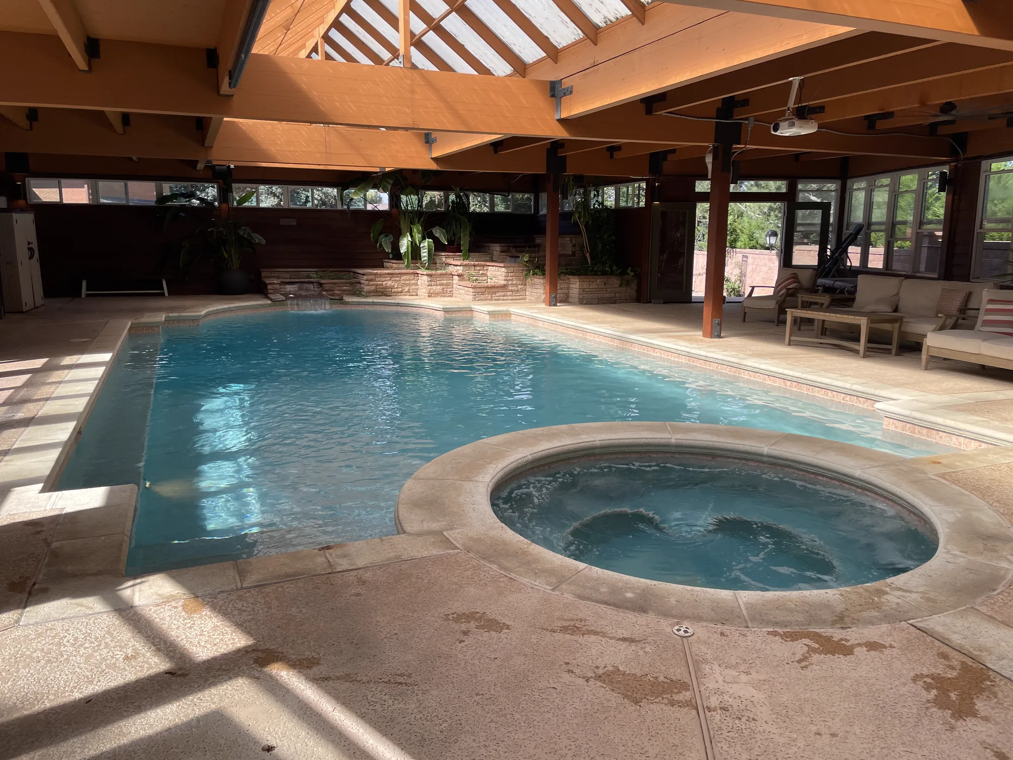
My indoor pool and spa.
Home Assistant orchestrates a controller I built around an ESP32. It runs two variable-speed pumps, automatic filling, sand filtration, boiler-driven heating through a stainless steel plate heat exchanger, and chlorination.
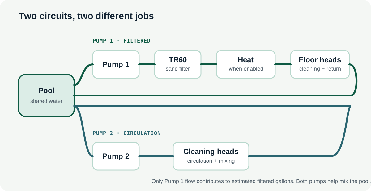
Pump 1 pulls from two skimmers and the floor drain. I can open or close those three sources independently. Water passes through the sand filter, then through sidecar loops for heating and chlorination when their diverter valves are open. Municipal water enters through an actuated autofill valve near the end of the train. A water-activated wave actuator is last, rotating flow through the floor zones and the cleaning heads on the shelf and steps before the water returns to the pool.
Pump 2 pulls from the floor drain only and runs a separate wave-actuated cleaning path. It circulates and mixes the pool, but it bypasses the sand filter and does not count toward filtered gallons. The spa and waterfall feature have their own pumps and are outside this analysis.
The functional topology. The valve order and sidecar loops are described above, but the accounting rule is simple: only Pump 1 sends water through the filter.
The data needed context
Before doing any math, I had to reconstruct what the equipment was doing when each reading was recorded. A temperature probe with Pump 1 off was measuring stagnant water in a pipe, not the pool. Several short autofill activations could be pieces of one refill. The same RPM could represent a different hydraulic state when a cleaning zone, skimmer, floor drain, or diverter valve changed.
I supplied the equipment specifications, sensor locations, plumbing, controller behavior, and historical logs. Codex used those details to separate useful events from misleading ones. That gave us two independent ways to estimate volume and another way to estimate flow.
A refill measured the pool
The controller already knew how many gallons of municipal water it had added. Because that water was colder than the pool, the mixed temperature response contained information about the pool’s thermal mass.
Fill volume + fill temperature + mixed pool response → estimated thermal mass → estimated volume
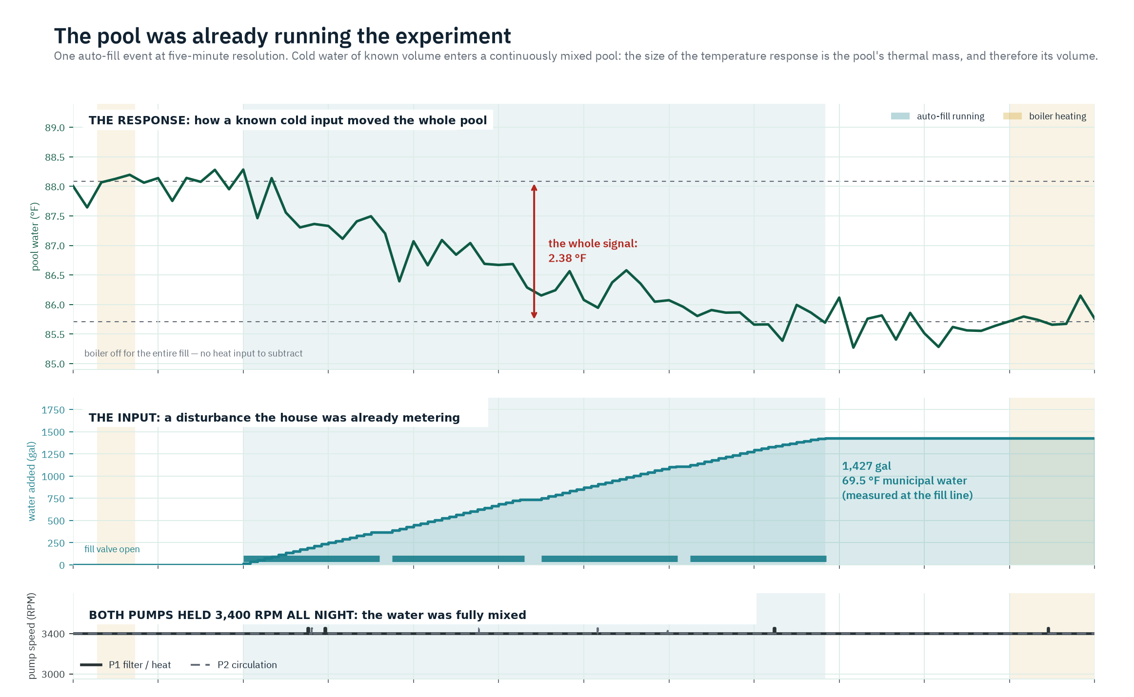
One of the cleanest events was a 1,427-gallon catch-up refill. When nobody is swimming, I sometimes put the pool in an off state and disable autofill. The water level then drops slowly over an extended period. When I turn the system back on, it may need a much larger refill than a normal daily top-off.
For this event, the incoming water was about 69.5 °F. Both pumps were running, the boiler was off, and the mixed pool temperature fell by 2.38 °F. After accounting for the cooling trend already underway, the refill history pointed to a pool near 28,000 gallons. The range was wide because an ordinary refill can look a lot like overnight cooling.
The refill becomes measurable once the pumps mix it through the pool. The chart shows the known water input and the resulting temperature change.
Heating measured it again
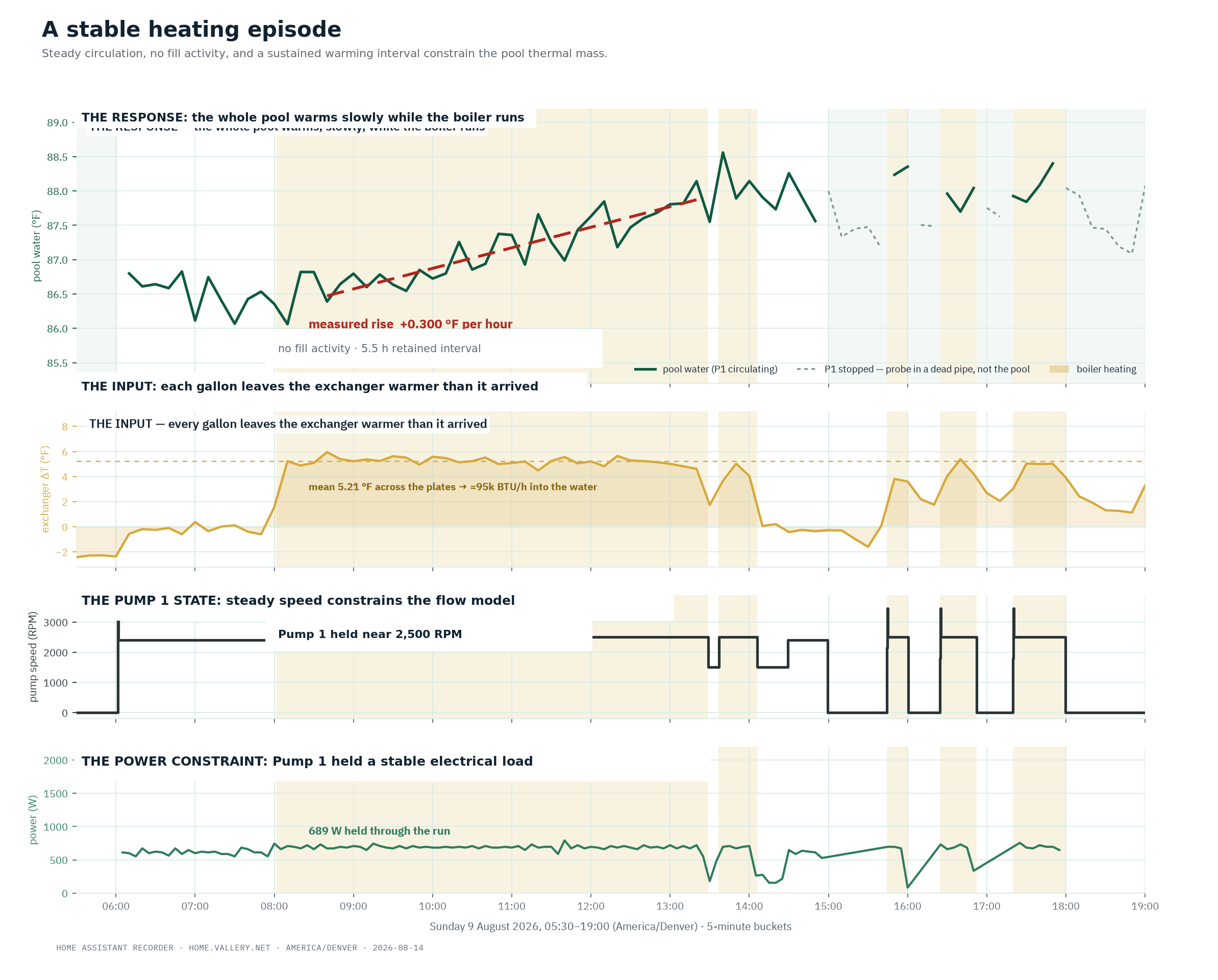
Heating provided a second way to estimate the same thermal mass. During a stable boiler run, the sensors recorded the temperature change across the heat exchanger and the rate at which the pool warmed.
Estimated heat transfer ÷ observed warming rate → estimated thermal mass → estimated volume
I kept runs with steady circulation, no fill activity, and enough duration to see the warming trend through the sensor noise. A clean August run produced 24,234 gallons. A clean June run produced 28,040 gallons. The other runs were less tidy, but together the heating data put the useful range at roughly 24,700 to 29,400 gallons.
The heating run provides an independent volume estimate. The pool’s warming rate and the temperature change across the heat exchanger constrain the same thermal mass as the refill.
Neither method was perfect, but their ranges overlapped. I adopted 26,600 gallons as the working value because it fit both sets of observations. It is still an estimate, and I can replace it if a direct measurement produces a better number.
RPM and watts became a flow sensor
The next problem was Pump 1 flow. RPM selects a pump speed curve, but it does not tell me where the plumbing operates on that curve. Flow also depends on the resistance of the sand filter, heat exchanger, pipe, fittings, cleaning zones, skimmer valves, floor-drain valve, and diverter valves.
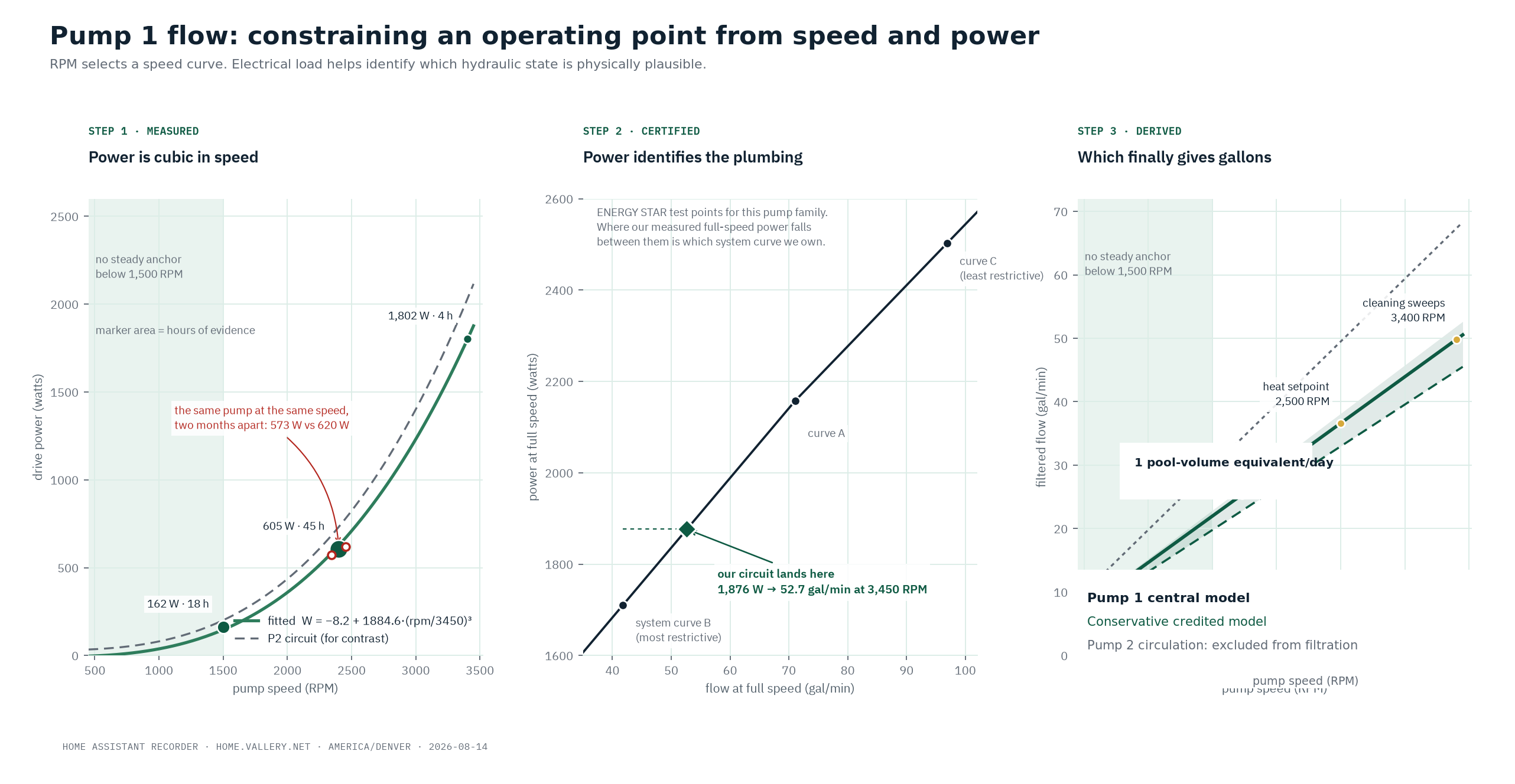
Pentair’s published performance curves supplied possible operating points for the IntelliFlo VS at each speed. The EPA’s ENERGY STAR test record connected tested speed, flow, and power. The TR60’s published 63 GPM commercial rating set an upper limit for the filter.
The controller uses two equations. The first describes the expected electrical load at a given speed:
W_fit = -8.2 + 1884.6 × (RPM / 3450)^3
The conservative baseline flow equation is:
GPM = 0.01319 × RPM
The flow coefficient is 10% below the central estimate of 0.01465 gallons per revolution. Watts do not appear in the second equation. They tell the controller whether that coefficient applies to the current hydraulic state. For each sample, it compares reported watts with the expected load for that RPM. If the reading fits the baseline state, the controller applies 0.01319. If it does not, the sample is not credited until that state has its own coefficient.
At 2,400 RPM, Pump 1 averaged about 573 watts during one period and about 620 watts during another. The filter may have been cleaner, a different cleaning zone may have been active, a diverter valve may have moved, or the open skimmer and floor-drain valves may have changed. The RPM stayed the same, but the hydraulic circuit did not.
RPM estimates flow; watts identify the operating state. The measured load shows whether the baseline flow coefficient applies.
How the controller works now
Home Assistant now turns each valid Pump 1 sample into estimated filtered gallons:
Estimated filtered gallons = Σ(Pump 1 inferred GPM × minutes in each valid state)
One pool-volume equivalent means that an aggregate volume equal to the pool has passed through the filter. Because the water is mixing continuously, it does not mean that every molecule made exactly one trip.
The controller stores the 26,600-gallon volume and the hydraulic coefficients as model parameters. It accumulates pool-volume equivalents instead of pump minutes. Normal operation can favor efficient lower-speed runs, while heavy use, extreme heat, or algae cleanup can raise the filtration target. Turnover does not replace sanitizer, pH, stabilizer, or the other parts of water chemistry; it gives the controller a better way to manage circulation and filtration.
I still want to compare the model with a temporary flow meter across several known valve states. Future refill and heating events will keep testing the volume estimate, and repeated observations as the filter loads will show whether I need another flow coefficient.
What AI changed
I thought I had two missing sensors and needed new hardware. Codex recognized that the existing telemetry already contained indirect measurements of both quantities.
That reframing was the useful part. A refill log collected to manage water level also described a known thermal disturbance. Temperature probes installed for heating also measured the pool’s response. RPM and watts collected to operate the pump also carried information about its hydraulic state. None of those signals was enough by itself.
Connecting them required moving between several engineering disciplines and understanding how this particular system was built. I did not know which specialists or search terms would have led me there. Codex did, and it turned the result into equations I could put into the controller.
The controller now does what I wanted from the beginning: it runs filtration based on estimated water processed instead of elapsed minutes. I can keep testing and improving the models, but I no longer need to treat a missing physical sensor as the end of the problem.